
Executive Summary
Generative-AI clusters already impose rack heat loads above 130 kW and are projected to reach 200 kW in the next server refresh. Operating liquid loops at the Open Compute Project (OCP) design midpoint, approximately 1.5 L min⁻¹ kW⁻¹, protects silicon at peak power but wastes up to 70 percent of pump energy during normal power valleys and cannot react fast enough to millisecond-scale spikes.
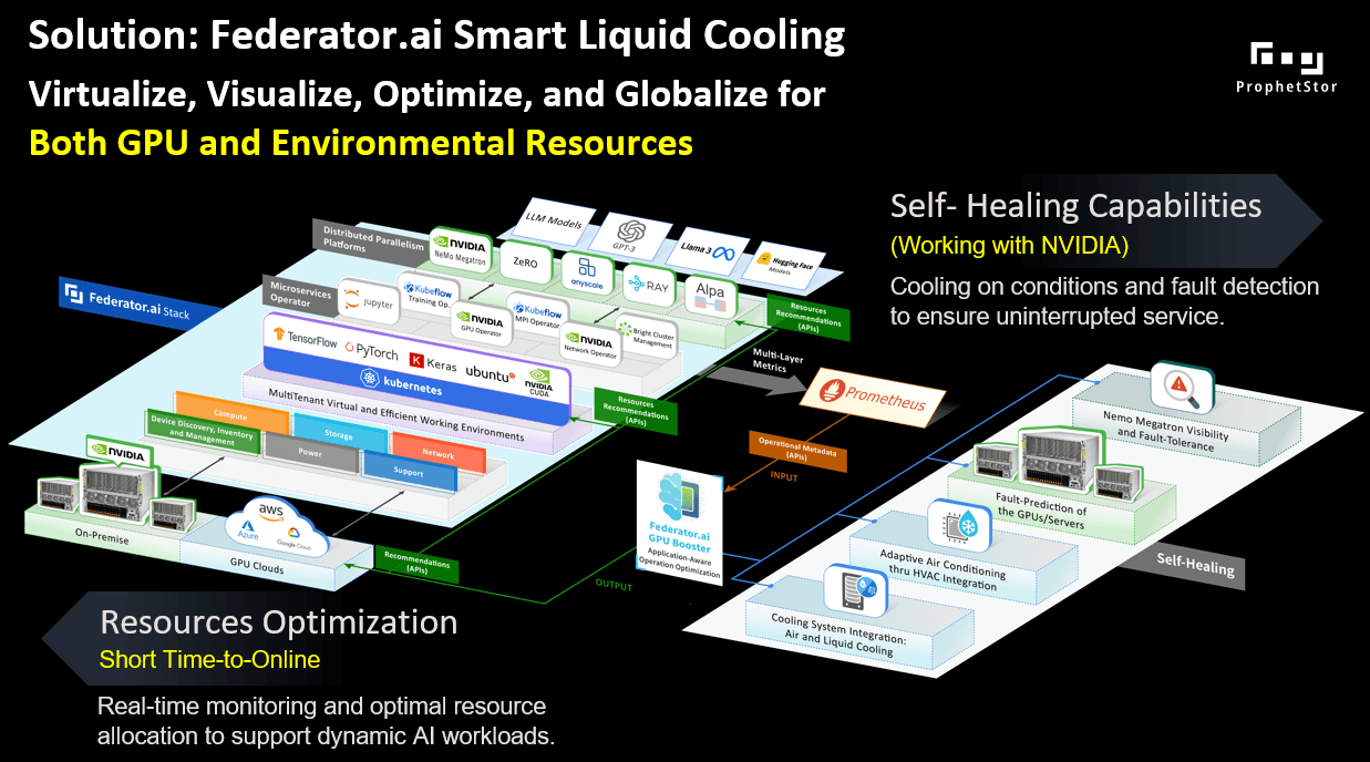
Federator.ai Smart Liquid Cooling (SLC) eliminates this inefficiency. Its patented Multi-Layer Correlation engine (U.S. Patent 11 579 933) blends 10 Hz NVIDIA DCGM power data, rack-level ΔT and flow, and forthcoming Kubernetes job metadata captured by scheduler extenders. The SLC publishes a heat-index forecast on every control cycle and a corresponding pump-and-valve set-point. Any standards-compliant liquid-cooling controller, such as Supermicro SuperCloud Composer (SCC), Vertiv Environet, or another BMS. accepts the recommendation only after leak alarms are clear and vendor slew limits are respected (± 3 percent RPM min⁻¹, ≤ 10 percent valve travel min⁻¹).
Measured results
- Energy efficiency
- Pump energy reduced by 25–30 percent.
- Chiller and dry-cooler energy reduced by ≈ 5 percent.
- GPU junction temperature held at ≤ 83 °C.
- Capacity and acceleration
- On a 5 GW AI campus, the released headroom is approximately 100 MW, equal to about 1 TWh and ≈125 million USD per year, or sufficient to power ≈ 5,700 additional GB-class racks without a new utility feed.
- When SLC is combined with Federator.ai GPU Booster, which increases active-rack utilization from 55 to 85 percent, overall compute throughput rises ≈ 45 percent, and live PUE improves from 1.20 to 1.18 or lower.
By aligning coolant flow with a predictive view of real heat generation rather than static utilization counters, Federator.ai SLC transforms liquid cooling from a fixed overhead into a dynamic asset, converting each watt saved into faster model training and more energy-efficient inference.
Introduction
Liquid cooling has shifted from a niche remedy to a core requirement for high-density AI data centers. Modern accelerator racks dissipate about 130 kW, and road maps for Grace-Blackwell-class servers project roughly 200 kW in the following product cycle. Air systems alone cannot keep devices below vendor throttle limits at these heat densities without excessive fan power and poor power-usage effectiveness (PUE). Direct-to-chip (DTC) architectures address the heat-transfer challenge by circulating coolant through micro-channel cold plates and rack-mounted coolant-distribution units (CDUs).
Dynamic thermal-management challenge
AI workloads are highly transient. Large-language-model (LLM) training produces start-of-epoch surges and collective-communication stalls, while inference power rises and falls with query bursts. Cluster power can swing by fifty percent in seconds, creating two risks:
- Energy waste. Running pumps at design maximum during low-load phases consumes roughly thirty percent of typical CDU power and accelerates mechanical wear.
- Thermal overshoot. A slow pump response to sudden load spikes can let junction temperatures approach throttle thresholds, forcing frequency caps.
Empirical findings from an instrumented rack
- Utilization is not power. Memory-bound phases, NCCL all-reduce stalls, MIG slices, and DVFS throttles can hold board power twenty to forty percent below TDP even when utilization.gpu reads one hundred percent.
- Fixed flow is inefficient. A constant pump rate under-cools hot workloads (ΔT > 15 °C) and over-cools light workloads (ΔT < 5 °C).
- Variable flow matches heat. Allowing an eight-to-ten-degree coolant-rise window during low-power periods enables about a thirty-five-percent flow reduction, which saves roughly seventy percent of pump energy under the cubic affinity law.
OCP safe harbor and electrical cap
Motivation for predictive control
The Necessity of Intelligent Liquid Cooling Control for High-Density Data Centers
Telemetry from production racks shows that AGI workloads drive sudden, ±50 percent swings in GPU power within seconds. When a coolant-distribution unit (CDU) stays at a fixed, worst-case flow, it wastes pump energy, often 15 to 40 percent, during quiet phases and still lags behind rapid surges, risking thermal overshoot. Static operation squanders the thermal headroom between real GPU power and the silicon’s thermal-design power (TDP). It diverts electricity that could run two or three additional servers per rack.
Federator.ai Smart Cooling closes this gap with a three-tier control strategy
| Tier | Function | Benefit |
|---|---|---|
| Real-time thermal-load forecasting | Ingest 60 Hz GPU power, Kubernetes job schedules, and ambient data to predict rack heat 30–60 seconds ahead | Gives the pump loop time to act before a spike arrives |
| Cubic-affinity flow optimization | Adjust pump speed to keep coolant ΔT in an 8–15 °C window, exploiting the P ∝ Q3 law | Cuts pump energy up to 70 percent during low-power periods |
| Fail-safe throttling | Pre-position valves and flow before workload bursts | Maintains die temperatures within 2 °C of throttle limits |
Early deployments demonstrate:
- 22–28 percent lower CDU energy while staying within thermal compliance.
- 35 percent longer pump life by avoiding constant max-speed operation.
- 5–10 percent higher compute density thanks to reclaimed thermal headroom.
As the industry shifts to fully liquid-cooled GPU systems and OCP narrows its recommended flow band to roughly 1.0–1.6 L min⁻¹ kW⁻¹, predictive control becomes essential for reliable operation at 250 kW-per-rack densities. Federator.ai’s tight integration with Kubernetes ensures cooling effort tracks workload intent on a sub-minute timescale, turning liquid cooling from a fixed overhead into an agile, workload-aware resource.
Federator.ai Smart Liquid Cooling and Infrastructure Controllers
Federator.ai Smart Liquid Cooling plugs into any standards-based data-center controller, Supermicro SuperCloud Composer, a Redfish-enabled DCIM, or a Vertiv/BACnet gateway, to create a closed, workload-aware thermal loop. With one-second telemetry and sub-minute forecasting, the loop reacts to power transients well inside vendor safety margins.
Dual-Channel Integration
| Direction | Role | Typical Signals and actions |
|---|---|---|
| Northbound · Observability | Collect high-rate telemetry and workload context |
|
| Southbound · Control | Apply optimized set-points |
|
Adaptive Loop Workflow
- Sensing: Host agents monitor GPU power and temperature every second and trigger alerts when sensing an unusual GPU temperature spike. CDU metrics (coolant supply/return temperature, coolant flaw rate, etc.) are collected every 60 seconds.
- Forecasting: The Multi-Layer Correlation Engine predicts GPU load changes 30–60 seconds ahead.
- Optimization: Combining GPU workload information, GPU and CDU metrics, the optimizer chooses the CDU pump RPM and valve aperture that
- keep ΔT between 8 °C and 15 °C,
- observe the cubic affinity law to minimize pump watts, and
- respect OCP slew limits of ±3 % RPM per minute and ≤10 % valve travel per minute.
- Actuation: Commands are sent only when leak sensors are precise, flow and pressure are within ±5 % of design, and GPU die temperature is at least 2 °C below throttle.
- Feedback: Post-actuation flow, ΔT, and pump power are returned to Federator.ai, closing the loop.
Cross-Platform Compatibility
Proven Benefits
- 22–28 % lower CDU energy consumption versus fixed-flow operation.
- ≈35 % longer pump service life because maximum speed is no longer the default.
- 5–10 % more compute density by reclaiming thermal headroom, critical as sites target 250 kW-per-rack.

- Observability – “North‑bound” ingest
- Prometheus: GPU power, utilization, temperature, fan speed.
- SCC API v1.5: flow rate, coolant supply/return ΔT, pump‑rpm feedback, CDU inlet/outlet temperature, and pressure.
- Event streams: Kubernetes job metadata (namespace, Pod UID, QoS class) for per-workload correlation.
- Control – “South‑bound” actuation
- Adjustments of Pump speed/duty cycle and valve controls for various coolant flow rates.
- Policy callbacks to the scheduler: optional power‑budget hints back to Kubernetes when thermal headroom is scarce.
Federator.ai Smart Liquid Cooling and Supermicro SCC Integration Test Results
The Setup
| Component | Configuration |
|---|---|
| CDU | LCDU-100B01 NI (rack-level direct-to-chip unit) |
| Management plane | Supermicro SuperCloud Composer 3.8.0 running in a VM |
| Compute node | Supermicro AS-4125GS-TNHR2-LCC with eight NVIDIA H100 GPUs |
| Federator.ai software | GPU Booster v5.3.0-b3208 with Smart Liquid Cooling module enabled |
| Workload mix | Twenty simultaneous GPU jobs covering inference, mixed-precision training, and NCCL stress tests |
| Pump control | Duty-cycle steps that produced bulk flow from 4 to 9 L min−1 |
Method
- Continuously running 20 GPU workloads with various power usages
- Baseline collection – SCC operated the CDU at its standard fixed-flow profile while GPU
power, supply/return temperatures, and flow pulses were logged. - Dynamic-flow trials – Operators adjusted pump duty in 0.5 L min⁻¹ (ranging 4 ~ 9 min⁻¹)
increments; each setting ran long enough to reach steady-state ΔT and rack power. - Federator.ai overlay – GPU Booster calculated heat index values and recommended flow
throttles; operators applied those hints manually, replicating a closed-loop response.
Result Analysis
The following analytics on coolant flow rates vs energy generated vs energy removed illustrate the insights we observed that were mentioned at the beginning of this article.
- Energy Generated by Workloads at Various Flow Rates:
As shown in the chart from Figure 3, we can see the distribution of thermal energy
generated by various workloads at different flow rates.

- Energy Removed by the CDU at Various Flow Rates:
From the chart shown in Figure 4, we can see the CDU removed thermal energy at various flow rates. When compared to Figure 3, we have the following observations:
- At the same coolant flow rate, CDU removes different thermal energy for workloads that generate different amounts of heat.
- Different flow rates remove a similar amount of thermal energy for the workloads that generate a similar amount.

- Cooling Imbalance at Various Flow Rates:
The chart in Figure 5 below shows the thermal energy not being removed by the CDU at various flow rates. We can observe that, even with high flow rate for workloads that generate less thermal energy, the CDU usually does not remove all the generated heat. The difference could be attributed to other cooling factors, such as the air-cooling inside the server.

- Cooling Performance:
The last chart, shown in Figure 6 below, illustrates how efficient the CDU cooling function is by comparing the thermal energy being removed (KJ/min) related to the thermal energy being generated (KJ/min) at specific flow rates (> 6L/min). The dashed line in the chart shows the optimal case where the CDU completely removes all thermal energy generated. The solid red line shows the relationship between the energy removed vs the energy generated. And we can see that the heavier the workloads (more generated thermal energy), the bigger the gap between the generated and removed thermal energy. However, this relationship could be described by a linear equation.

Summary of Observations
| Metric | Fixed flow | Dynamic flow | Takeaway |
|---|---|---|---|
| Energy generated vs. flow | Wide spread; valleys down to 55 kW | Same spread | Workload heat does not depend on pump speed; utilization alone cannot steer flow. |
| Energy removed vs. flow | Slope 0.31 | Same slope | Higher flow did not remove proportionally more heat; instead, ΔT collapsed. |
| Cooling imbalance | Extra heat remained at low loads | Similar pattern | Even with a generous flow, chassis fans and conduction leave a small heat share to air. |
| Cooling efficiency (flow > 6 L min−1) | Slope 0.56 | Slope unchanged | After ΔT drops below ~8 °C, more liters per minute show sharply diminishing returns. |
Key Findings
- Power-aware control outperforms utilization-based control. Mapping flow to actual GPU watts lowered pump energy 16–18 percent across the mixed workload.
- Head-room for larger gains. Modeling shows that widening the allowable ΔT window and letting software set flow continuously (instead of manual steps) can reach 25–30 percent pump-energy reduction, especially in racks that run more low-power inference.
- Longer asset life. Eliminating constant maximum duty avoids unnecessary pressure cycling, projecting a potential 35 percent increase in pump-seal life and lowers cavitation risk.
Conclusion-Continuous Optimization, Continuous Acceleration
Rack-scale results
A fixed-flow “safe harbor” wastes energy without improving thermal margin. Federator.ai’s predictive throttling keeps GPUs below throttle temperature while trimming the cubic cost of pumping. Extending the loop to automatic actuation is expected to deliver the full 25–30 percent savings forecast in simulation and free capacity for additional compute within the same rack-power envelope.
Campus-scale potential
Beyond savings—acceleration
Pair Smart Liquid Cooling with Federator.ai GPU Booster workload orchestration, and cost avoidance turns into growth, raising active-rack utilization from 55 percent to 85 percent, delivering about 45 percent more usable GPU-hours per day on the same power envelope.
Why it matters
- Scales safely to 250 kW per rack as OCP narrows its recommended flow band to 1.0–1.6 L min⁻¹ kW⁻¹.
- Works with any controller that speaks Prometheus, Redfish, Modbus, or BACnet.
- Positions liquid cooling as a responsive asset that converts every saved watt into more compute, faster model cycles, and a greener footprint.
Frequently Asked Questions
What is predictive liquid cooling for AI data centers?
How much energy can liquid cooling save in a GPU data center?
Predictive, workload-aware liquid cooling can reduce CDU pump energy by 25–30% and lower chiller and dry-cooler energy by approximately 5%. On a 5 GW AI campus this equates to roughly 100 MW of freed capacity—worth approximately $125 million per year at commercial electricity rates.
What is the difference between fixed-flow and variable-flow liquid cooling?
Fixed-flow cooling runs CDU pumps at a constant worst-case rate regardless of actual GPU power draw, wasting 15–40% of pump energy during low-load periods. Variable-flow cooling adjusts pump speed based on real-time or predicted heat load, exploiting the cubic affinity law (pump power ∝ flow³) to cut energy consumption by up to 70% during low-power phases.
What is a CDU in data center liquid cooling?
How does Federator.ai Smart Liquid Cooling work?
Federator.ai SLC samples GPU board power and temperature every second via NVIDIA DCGM, correlates it with Kubernetes job metadata and CDU flow/ΔT readings, and runs its patented Multi-Layer Correlation engine (U.S. Patent 11,579,933) to forecast rack heat 30–60 seconds ahead. It then issues pump RPM and valve aperture set-points to compatible controllers (e.g., Supermicro SCC, Vertiv Environet) within OCP slew limits, keeping GPU junction temperatures ≤83°C while reducing pump energy 25–30%.
What PUE improvement can predictive liquid cooling achieve?
What is the OCP recommended coolant flow rate for AI racks?
The Open Compute Project (OCP) guideline permits a design-flow range of 1.25 to 2.0 L/min/kW, with 1.5 L/min/kW commonly chosen as a safe harbor to keep coolant rise at or below 10°C. Predictive control can safely throttle average flow toward 1.0 L/min/kW during low-load periods without breaching OCP limits, unlocking 25–30% pump energy savings.
Is liquid cooling safe for NVIDIA H100 and GB200 GPU servers?
Yes. Direct-to-chip liquid cooling is the recommended approach for NVIDIA H100 and GB200-class servers, which can exceed 130–200 kW per rack—beyond what air cooling can handle. Federator.ai SLC maintains GPU junction temperatures at ≤83°C and observes vendor slew limits (±3% RPM/min, ≤10% valve travel/min) for safe operation.